Spectra IV  Repair Page 1

|

|

|

|

|

|
|
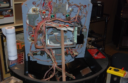
Bringing the machine home was quite a task for the kids and I. According to the documentation this machine is just over 38 inches squaure and weights in at approximately 196lbs. But we
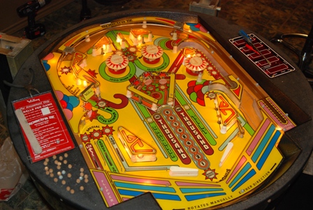
managed to get her out of the truck and into the ManCave with out to much trouble. I took a few photos which will be presented to right and below this paragraph. The machine was dirty
but all the parts appeared to be there. Along with the machine came one of the key lock retaining pins the secure the top to the legs. Having this retaining pin loose from the machine was
a good thing as there were no keys supplied with the machine. We plugged it in and saw all the lights come and and thought... coooool! But we were quickly dissappointed as we made all sorts of attempts to wake up the machine so we could play with it. The machine cabinet and glass was in decent shape and it's appearance and size fit very well in the ManCave. |
|
|
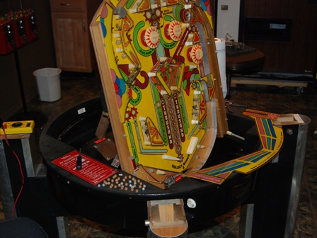
We haven't decided yet if the machine will be brought into the GameRoom in the house. I figured it would be best to have the machine near the shop and all my tools as worked to repair
her. The first order of business was to try and access the internals of the machine. Attempting to pick the lock with my extremely limited knowledge proved futile. But since I had that one
retaining pin lock I took it the next day to a local locksmith. An hour or so later I receive a call and was told that they now had a key that would fit my lock. Picking up the lock, I paid the man a mere $8 and hurried home. I suspected that the remaining retaining pin locks would be keyed the same. There is one on each leg of the table. Soon after arriving home, I had all the retaining pins out and the glass top off and leaning against a pachinko cabinet. While my suspesions were correct about the locks on the retaining pins being the same, that was not true for the side credit door and the coin box door. |
|
WIth the top off the machine it was time to evaluate what I had to work with. All the components appeared to present and accounted for. Both balls were in the machine as well. My initial evaluation came up with the following: A. Rubber replacement - all were either broken or hard and cracking B. Ball cleaning - the two balls has small surface rust C. 3x Bonus - This plug for this light had come loose D. Kicker Spring - missing from the far left kicker solinoid E. Plastic cleaning - a brownish hard film covered it all F. Lights - some lights appeared to non-functioning G. Credit Door - no key for this door H. Coin Box - no key for this either I. Rotation - movement was rough and possibly causing play issues J. Demand Button - top of this button is missing K. ????? |
|
|
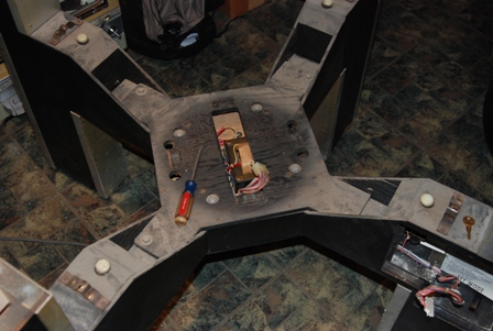
As with my other restoration projects I have found that if I start cleaning it I tend to repair as I go along and unfortunately find other things to fix too. So my first order of
business was to pull the play field out of the tub and the seperate the tub from the table structure. Once this was done, I cleaned up the rotation contacts and oiled the 'lazy Susan'
style bearings. While it was apart I also cleaned the rotational spring stops and white plastic bumbers that are also used to refelct the light for the rotation tilt device. I then
put the tub back and plugged it back in. With this done I have solved "I" as good as it's going to get. Next I put the playfield back into the tub to facilitate my working on it. Since the original prop stick was missing I made one. Now it was time to pull off the pretty parts and start cleaning. As I did so I removed all the rubber components in anticipation of new ones being acquired to replace them all. I also shinned up the top ball deflectors and the 'spinner gate'. I also spent a fair amount of time using steel wool on the two balls to shine them as much as possible which solved "B". |
|
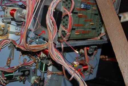
With the play field propped up, I turned my attention to the electronics. The card cage is rather unique in how one can access the cards. First you unplug all the edge connectors
then there is a small screw on the left hand side of the cage with a red dot next it that is removed. Once done, the pin connectors on top of the light driver board are unplugged and
pulled out of the way. Finally the card retaining sides can be rotated allowing each card to be pulled from the cage. As I pulled each card I inspected it for burned components, broken wires, etc. Both the light driver board and solinoid board passed this visual inspection. The CPU card however was a different story. As is VERY common on this machine, the NiCd batteries had leaked and the corrosion was spread across the board. This was really depressing as I am less than a novice when it comes to electronics. |
|
|
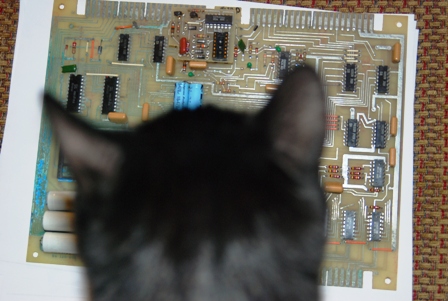
The first thing I did was to to take some photos of the CPU board so I could send to whom ever I could that might be able to assist me. Ninja decided that he too needed to review
the board to make sure I was doing everything correctly. After doing some research on the net, I found a gentleman that owns a machine like mine and posted he had a repairman working
on it. I made a quick call and go the repairman's phone and the next afternoon I was able to determine what my next steps were to be First, I cut off the batteries and tossed them. Secondly, I mix a solution of 50/50 Water and Distilled vinigar and put it in a spray bottle. I then sprayed the board with liberal amounts of this solution. It seems Vinegar is counter acts the chemicals that the NiCd leaks. I let it soak for a few minutes and then rinsed the whole board off with water. This is really counter intuitive, washing electronics with water. But.. if you give it plenty of time to dry... all is fine. In my case most of the corrosion came off and I then set about testing the affected printed circuits. |
|
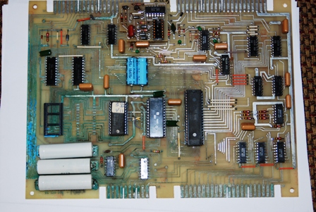
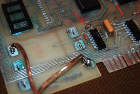
As you can see in the photo the majority of the corrosion was on the left hand side of the board. I used my Digital Multi Meter (DMM) to check continuity and found one circuit that
was no longer functioning. All the other circuits seemed to be in good shape. I examined the chips and it did not appear that the corrosion had creeped up into them yet so I decided
to leave them be for the time being. Of particular interest, I reviewed the ciruit board and compared it to the schematic that was in the copy of the original technical manual (found
here) and discovered that that while close, there were some big differences. I figure these differences came about from the initial engineering design and the final manufactoring design. But, this did give me cause to think about that circuit that was broke. I looked at the circuit and determined that it traced from one edge connector to the edge connector on the other side of the board. I then looked at the pins on the edge connectors and discovered that one of them didn't have connection pins. This broken circuit isn't used on this rendition of the CPU card! Thus I don't have to fix it! |
|
|
While I was waiting for the circuit boards to dry, I pulled all the light bulbs and cleaned them. I also polished up the connection points on the lamp holders. In doing so I
examined the 3X light location and reglued it back in place. I'm concerned that it's too small for the hole now but hopefully the glue will hold it in place. Problem C resolved. I
also spent a good deal of time and Windex on cleaning the plastic parts. I tried to find a return spring for the left kick out solinoid but when I couldn't find one suitable, I made
one from some stiff wire I had in my shop. I simply wrapped it around a bolt that was close to the same size. This 'spring' isn't strong but it doesn't really need to be as the ball
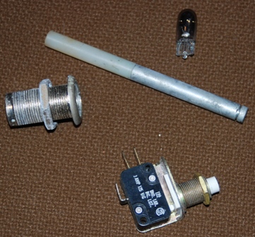
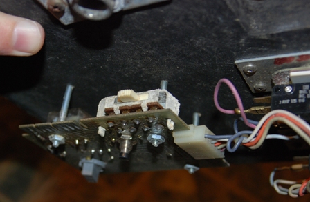
will push it back anyway. Problem D resolved. Next I turned my focus on the coin mech. door lock. Since this lock didn't match the leg locks nor the coin box lock, I simply drilled it and purchased a new one from Ace Hardware. It's nice to have one so close 5 blocks away! Once I got into the door, I found that the Test/Play/Set switch had lots of 'powdery' stuff on it. Since my continuity checks proved that the switch was working properly, I have opted to leave it alone for now. Test on the 'Add Credit' and 'Demand' buttons were done and I found that the Demand button was not making contact as it should. This could explain why the top of the button was broke! I replaced this with one from Radio Shack but am not happy with the asthetics of it so I will eventually find a better replace. But for now, I'll call problems G and J resolved. |
|
Once the CPU board had a few days to dry, I then (in my haste) put it all back in the card cage and mounted the other two boards as well. Powering up the system, I got 4 quick beeps
and then nothing. This was less than I had before. I tryed to thing what I missed.. then remembered that while I cut the batteries out I had not replaced them. That's what I get for
being in a hurry. So, I pulled the cards back out again which I convinced myself would help the edge connectors become better connected! I purchased a 4 AA battery box from Radio Shack
and soldiered some wires onto the CPU board where the batteries were. Since the box is made to fit for batteries I soldiered a jumper wire across the 4 position. Looking at the board, it appeared that one of the disc capacitors didn't look to healthy, but again, in my haste, I decided to put it all back together and see what happens. Maybe it just looked bad. Once I had the boards back in, I used wire nuts to connect the battery box to the wires from the CPU card. This will allow me to pull the boards if necessary with out having to drag the battery box along with it. Putting it all back together, I powered it up. This time I sound, a few solinoid pops and the display showed a bunch of 7's on it. This is more response that I've had since I got the machine so I figure I'm making process. Only A and G problems remain of the original list, however, the following problems are now added. K. Bad capacitor on CPU board L. Testing/Adjusting of rotational tilt |
|
|
Well a quick run to Fry's at lunch and I purchased a 22pu Capacitor as this is what the schematic called for in the manual. When I got home, I found the rubbers that I had ordered
were in the mailbox. So, the first thing I did was the easy stuff... I put the rubbers on the machine. In doing so I realized that I have 4 rubbers that fit around the full size
post that I did not order. Tomorrow I will order those and with those I can mark off problem A. I then pulled out the boards and started to work on the CPU board. You can see in the photo the arrow is pointing to the bad capacitor. I cut it off and then desoldiered and pulled then remaining wire from the circuit board. I inserted the new cap, resoldiered it and cut the excees wires off. I then put all the boards back into the card cage, reconnected the batteries, laid down the play field and plugged her in. Then came the moment of truth. I turned on the switch, a long series of low tone beeps and 7's on the display board... and that was it. |