GE Mr. Christmas Wireless
 Lights and Sounds of Christmas
Audio Plug Installation
|
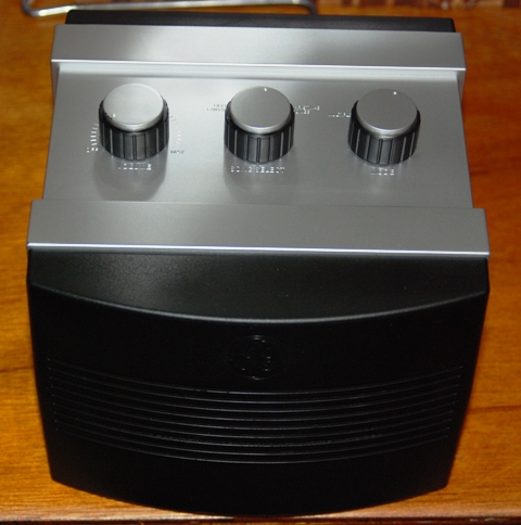
Purchased from Lowe's for around $130, the GE Mr Christmas Wireless light animation system was just the low cost system I was looking for. However, once I got it home and began to do some research I learned that the system only plays the music through built in speaker on the main unit. Well, that's fine for an occasional use, but running it every night will become a huge aggravation for the neighbors. So I began to research alternatives and decided that I would connect it to an FM transmitter so people can listen to the music in their cars instead of having it blasted across the neighborhood. Unfortunately, the system does not have a external audio jack, so I set about installing one. This web page will show you how I did it. In hindsight, I should have installed a 'cut out' jack that would remove the sound from the built in speaker whenever the jack was used. Maybe next year. You will need the following toos: Small phillips screwdriver, long shafted medium phillips screwdriver, soldering iron. knife or other means to strip some wire, a 1/8" audio jack, small section of single pair wire, drill and appropriate sized drill bit. |
|
|
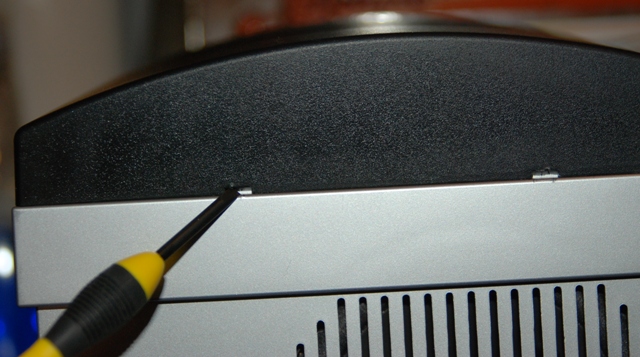
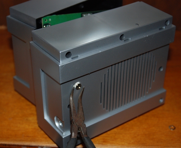
The main unit is divided down the center and will come apart in two major pieces allowing access to the internal components. However, it doesn't give up it's guts easily. The first step is to remove the front 'decorative panel'. This is done by inserting a screwdriver into the two small gaps in the cover and prying upward and outward. This part fits tightly and requires some effort and restraint to prevent breakage. Once you have this piece off, set it to the side to hold the screws you are about to remove. |
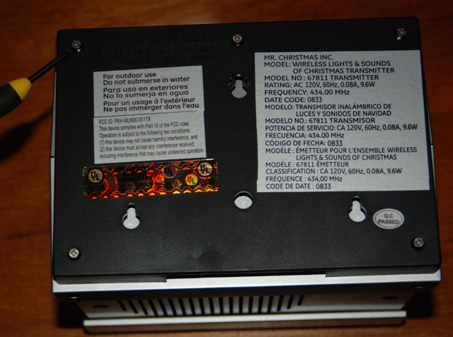
| Next, remove the rear support panel. This piece is designed to facilitate the mounting of the system to a flat wall or the supplied ground post. Simply unscrew the 5 screws as shown in the photo. Note that these screws have 'counter sink' styled heads and place them in the front cover. |
|
|
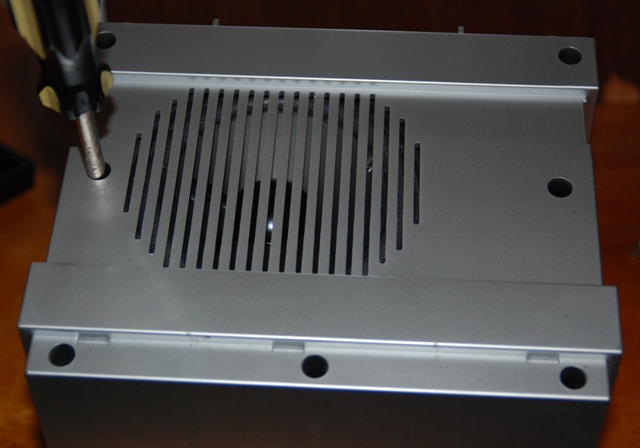
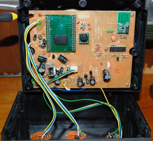
With the back piece removed, you now have access to all the screws that hold the two major halves of the system cabinet together. These screws are deep inside the holes. As you can tell in the photo, you will need a long shafted phillips screwdriver with a medium point to reach them. Remove all screws noting they have flat heads on them. Place them into the front cover with the others. |
| Carefully pull the two pieces of the cabinet apart being aware of the wiring that ties all the components together. Once apart, you will see where the printed circuit board is attached by 4 screws, one at each corner. Remove each of these and set them in the front cover. Note that these are the smallest screws you will remove. |
|
|
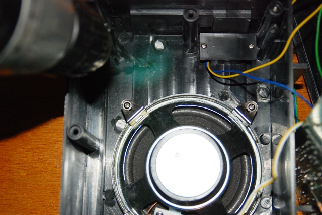
Now that we have the two pieces seperated, you can locate where you want to place the audio jack. I chose to place mine on the opposite side from the speaker and on the BOTTOM of the cabinet. This location kept my drill away from any vital components AND put the jack under the bottom to prevent water from seaping into the cabinet. Using a drill bit slightly larger than the jack required, carefully drill through the cabinet and then test fit your jack. Do not install the jack yet, as this will only make the soldiering steps more difficult. |
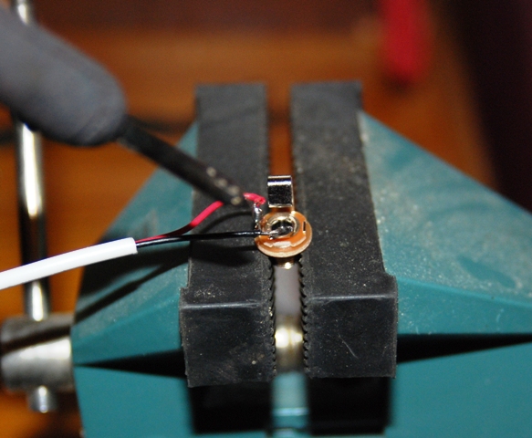
| With hole drilled, it is now time to do the electrical work. First, soldier the wires onto the audio jack. I used a single pair section that was left over from my home security system wiring and soldiered the red wire to the positive pin on the jack and black wire to the negative pin. On these jacks, the positive pin will connect to the END of the 1/8" plug and the negative to the longer base portion. |
|
|
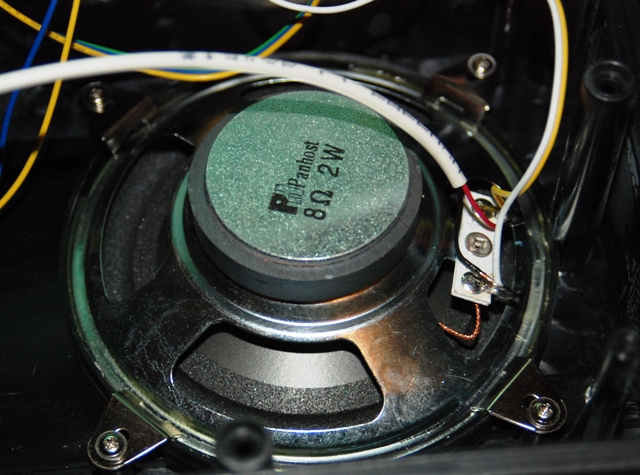
Since we have the iron hot, let's go ahead and soldier the wire to the speaker terminals. I simply heated up the existing soldier, pressed the wire to it and then added a bit more soldier just for good measure. In hindsight, if I had installed a 'cut out' type jack, then I would have cut one of the wires going to the speaker (based on the type of jack) and soldiers one wire to the speaker and the speaker wire to the jack point. On my system, the Positive and negative terminals were labeled on the speaker. |
| With all the wiring done and the soldier cooled, install the jack into the hole you just drilled and tighten. |
|
|
All done! Simply resverse the disassembly instructions to put it back together. Keep in mind that the smallest screws are for the circuit board, the 'flat head' screws are for the cabinet pieces and the 'counter sink' screws hold the back on. That's it, you now have an external audio jack on your Mr. Christmas. Since I will be attaching a stereo FM transmitter, I will be using a mono-to-Stereo jack adapter to send audio to both channels. I considered using a stereo jack on the install but decided to make the jack match the interals for system consistancy. I hope you find these modification instructions useful and good luck with your Christmas Project! Merry Christmas! |
|
